Beampattern#
Although a spherical source is the simplest type of sonar source, the most common man-made sound sources used in underwater acoustics are planer transducers which have flat surfaces which oscillate to produce sound. This is in part due to the fact that a flat transducer is relatively easy to manufacture, but more importantly, the transducer transmits a majority of the sound in the direction perpendicular to the vibrating plane. This is a useful property in many sonar systems in that this directionality can help determine the location of an object (fish, bubble, submarine, etc.)
The circular piston transducer#
Note that we said the transducer directs a “majority” of the sound in one direction and not “all” of the sound. In fact, the transducer sends different levels of sound in many directions and the directional dependence of the sound is refered to as the transducer’s beam pattern. To help understand the concept of a beam pattern and it’s properties, we will focus initially on one particular, common type of tranducer: the circular piston. This type of transducer is often a cylindrical piece of piezoelectric material to which an electrical signal is applied such that it expands and contracts along the axis of the cylinder. The causes sound to radiate from the circular face of the transducer. The structure of the sound field from this type of transducer can be fairly complicated and there is not a simple, mathematical expression for the direction and strength of the transmitted sound. There are, however, approximate mathematical descriptions that can accurately describe the transmitted sound under certain conditions. One of the most useful of these is to assume that the transducer can be approximated as a baffled circular piston. By “baffled,” we mean that the face of the transducer is surrounded by an infinite, rigid surface. This simplifies the mathematics and allows us to calculate the amplitude and direction of the transmitted field.
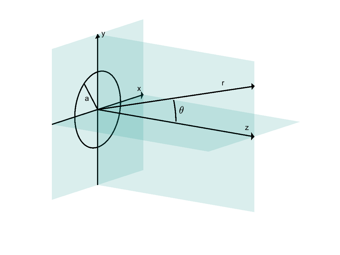
In the following, the face of the transducer will be in the x-y plane and the z-axis is perpendicular to the face. The radius of the tranducer is a and the field will be described in two ways; either a function of the distance, r, from the center of the face and the angle, \(\theta\), between the direction of r and the z-axis or as a function of distance from the plane of the transducer (range) and the perpendicular direction (cross-range.)
If the sound is measured far away from the face of the transducer, the intensity of the sound will be proportional to \(1/r^2\) and the angular-dependence of the field can be expressed in a simple form that does not depend on the distance. When the reciever is sufficiently far away that these two properties are true, then the receiver is said to be in the far-field of the transducer. In the widget below, we’ve removed the \(1/r^2\) dependence and normalized the intensity by the value measured on the z-axis or \(\theta = 0^\circ\). As a result, the normalized intensity is 0 dB (or 1 on a linear scale.) The widget allows you to make the transducer larger or smaller by increasing it’s radius and allows you to change the frequency of the sound being transmitted. You can also display the angular dependence of the transmitted sound on different plots and on both a linear and decibel scale.
One of the things you’ll notice as you decrease the frequency or decrease the radius, is that the central part of the beam pattern gets wider. This central portion of the beam pattern that includes the maximum at 0 degrees and is enclosed by the first null (points where the level gets very low) is called the main lobe or main beam. Most of the energy of the transmitted sound lies in this beam. As a result, most applications try to utilize just this beam. A key parameter for the transducer is width of this main beam or the beam width. The beam width is defined as the width of the beam when the field drops to a set level below the maximum value. This level is sometimes defined as 3 dB, 6 dB, or 10 dB which on a linear scale corresponds to 1/2, 1/4, or 1/10 of the maximum of the maximum value of the main lobe. For example, SS510 transducer spec sheet states that when operating at 200 kHz, the beam width is 9 degrees @ -3 dB. The table above shows the beamwidth defined relate to the different levels for the plotted beam pattern.

Exercise
For the SS510 transducer, the spec sheet says that at 200 kHz, the beam width is 9 degrees @ -3 dB. Using the widget, can you estimate the radius of the transducer?
The other beams or lobes are often referred to as side lobes. Notice that while the shape of the main lobe and the side lobes change significantly with frequency and transducer radius, the maximum level of the two sidelobes on either side of the main lobe is always at the same level, 17 dB, or 1/50 of the main lobe. This doesn’t always hold true for all piston transducers but is a good approximation for the level of the first side lobe and is a useful rule of thumb for the far-field of the transducer.
The field of the piston transducer is calculated below as a function of range from the transducer face and cross-range. While the calculation above shows how the field behaves as a function of angle relative to piston’s center, this calculation shows how the field varies throughout the water in front of the sound source.
Other types of transducers#
Another common transducer design is a transducer with a rectangular face. For the circular piston, we saw that as we increased the diameter of the piston face, the main beam became narrower in all directions. For the rectangular piston, as one of the axes of the rectangle is lengthened, the beam in the plane parallel to that axis will also become narrower while the beam perpendicular to that axis remains largely unchanged. This can be really useful in situations where you want a narrow beam in one direction and a wide beam in the other direction. Side scan sonars use a rectangular transducer to make it possible to image using a beam projected from the side of towed sonar that is wide in the vertical direction but very narrow in the direction of the towed.